GOING DIGITAL
Learn why more LVDT position sensor users are designing systems utilizing digital outputs.
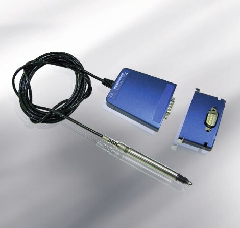
When using a sensor like an LVDT to monitor operating parameters such as movement and position, digital communications offer the highest accuracy as the output sensor signal is not easily degraded. Excessive noise generated from environments such as oil fields and turbines can cause incorrect results and non-linearity errors as analog systems become more complex. With greater immunity to noise, digital systems have an increased capacity to control errors and provide a complete signal from an LVDT and other sensors into computer software and other network programs.

In networked communications, digital communications allow for daisy chaining multiple signal conditioners on one bus line, reducing wiring costs; other benefits include reduced I/O cards and wiring, footprint, and weight. With an RS-485 digital output, longer cables, up to 4000 feet, can be used from the sensor to the data acquisition system, with several integrated along one cable instead of one sensor per cable. Longer cables enable the placement of sensors in harsh conditions with electronics securely located in non-volatile environments.
How to go digital
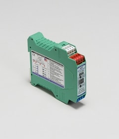
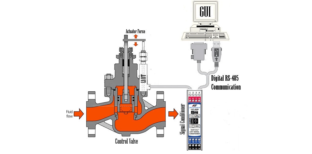
Digital outputs can be derived from any standard sensor using a signal conditioner designed to provide a RS-485 digital signal. For example, TE Connectivity's (TE) LVC-4000 LVDT / RVDT signal conditioner interfaces with wide range of AC LVDTs, RVDTs, and VR half-bridge position sensors and offers customers the option of using either a 4-20mA analog signal or a digital signal (RS-485). Both outputs can be used for different requirements or either based on user preferences. With the use of the RS-485 port, a host computer is able to retrieve measurement data, receive operational status, perform remote calibration, and perform hot swap re-configuration. Synchronization to other signal conditioners is accomplished by a daisy chain connection to a synchronization bus. One unit will assume the master function based on DIP (dual in-line package) switch priority setting. If a fault should occur, the next highest priority unit will take over as the master.