
White Paper
Evaluating Temperature’s Impact on APD LiDAR Sensor Behavior
This report provides information about typical avalanche photodiode (APD) properties with a range from -40° C to 125° C.

Overview
As LiDAR systems gain acceptance in autonomous vehicles, it will be essential to understand the impact of temperature on their sensors. These sensors must operate accurately and reliably in a variety of environmental conditions. Typically, automotive "grade 1" operating temperature range from -40°C to 125°C is required. This temperature range is needed for functionality considering sun-exposed positions for the sensor, self-heating of electronics inside the sensor and various ambient conditions worldwide.
The avalanche photodiode (APD) is a popular sensor technology that is rapidly becoming incorporated in LiDAR systems. This report provides information about typical APD properties for a range from -40° C to 125° C.
To use APD sensors in this temperature range, it is important to understand the dependence of the following parameters:
- Break down voltage (Vbr)
- Dark current (Id)
- Gain (M)
- Spectral responsivity (S)
- Dynamic behavior (rise time)
- Capacitance (C)
APD sensors manufactured in a common silicon technology have a significant temperature dependent behavior. Based on the physics of semiconductor materials, these dependencies have different physical properties.
In this overview, we describe three effects:
- Intrinsic electron hole pair generation
- Mean free path of electrons in the multiplication volume
- Probability of optically generated electron hole pairs
Intrinsic Electron Hole Pair Generation
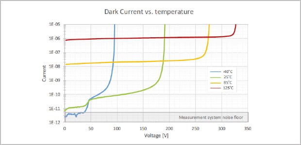
With increasing temperature, more electrons are excited from the valence band into the conduction band, which increases the reverse current flow in an APD sensor. This reverse current is equal to the dark current of the APD, when no light generates additional electrons.
Mean Free Path of Electrons in the Multiplication Volume
The mean free path of moving electrons in the multiplication volume of an APD is strongly dependent on temperature. The higher the temperature, the shorter the mean free path caused by faster moving atomic nuclei in the APD’s semiconductor material. The shorter mean free path decreases the probability to reach the impact ionization energy, which results in a lower gain at a fixed bias. The same mechanism increases the breakdown voltage with increasing temperature as well.
Probability of Optically Generated Electron Hole Pairs
Faster moving atomic nuclei within the APD semiconductor material increase the probability of colliding photons with atoms and generating electron hole pairs. This probability has a direct dependency on the quantum efficiency and therefore on the spectral responsivity for a fixed intrinsic layer thickness. For photons, which are not completely absorbed in the active area of the APD, the spectral responsivity increases with higher temperatures.

Temperature-Dependent Measurements
Breakdown voltage, dark current, gain, capacitance, and dynamic behavior measurements were applied to a TE Connectivity AD500-9 APD sensor with a breakdown voltage of 191 V.
| Temperature | Dark current (M=1, Vop=10V) | Break down voltage (Ibr =2 μA) |
|---|---|---|
-40 °C |
3.68E-12 A |
95 V |
25 °C |
1.06E-11 A |
191 V |
85 °C |
1.42E-8 A |
275 V |
125 °C |
7.87E-7 A |
322 V |
Table 1: Dark current and breakdown voltage for T= -40° C... 125° C
Dark Current and Breakdown Voltage
The first physical effect mentioned in the overview has a significant impact on the dark current. The higher the temperature, the higher the intrinsic electron hole pair generation. The dark current increases with higher temperatures. In figure 1, the dark current for a temperature of -40° C, 25° C, 85° C, and 125° C is shown for the AD500-9 APD. The second physical effect shifts the breakdown voltage Vbr to higher voltages. For -40° C, Vbr approaches 95 V and increases to 322 V for a temperature of 125° C. The change of breakdown voltage is a simple linear function. The according temperature coefficient is approximately 1.4 V/K. Table 1 shows the temperature dependence of Vbr. The dark current voltage characteristics for a temperature of -40° C for low voltages is determined by the noise floor of our measurement setup as marked with a grey rectangle in figure 1.
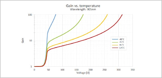
| Temperature | Voltage (M=100) |
|---|---|
| -40° C | 76.0 V |
| 25 °C | 174.0 V |
| 85 °C | 259.5V |
| 125 °C | 313.0 V |
Table 2: Dark current characteristics vs. temperature
Gain
The gain of the AD500-9 sensor for different temperatures is shown in figure 2. The same effect, which shifts the Vbr to higher voltages, also shifts the optimum gain to higher operating points. The mean free path of electrons decreases with higher temperatures. This effect decreases the gain for a fixed voltage. Higher operating points are necessary to reach a certain gain. The gain curve is steeper for lower temperatures. In this case, the mean free path of electrons is so high, that lower voltages provide sufficient acceleration to reach the impact ionization energy. The gain increases faster for increasing voltages.
Spectral Responsivity
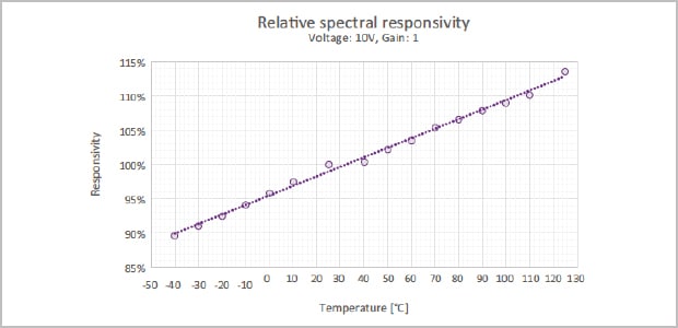
The spectral responsivity slightly increases with higher temperature. This is caused by a higher probability of generating electron hole pairs if not all of the optical power is absorbed in the semiconductor material. Figure 3 shows the trend of the spectral responsivity relative to the responsivity for 25° C. It is shown, that the responsivity increases with increasing temperature.
Capacitance
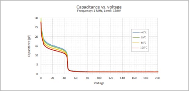
The capacitance curve provides information about the capacitance for different voltages. It is an important parameter for the dimensioning of receiver circuits, and has a high influence on the APD sensor’s dynamic behavior. Figure 4 shows capacitance trends for an AD500-9 APD sensor, measured with a LCR meter.
The measurement frequency is 1 MHz with an amplitude of 15 mV. The behavior shown in Figure 4 could be explained with the help of a plate capacitor. The thickness of the depleted zone represents the thickness of the plate capacitor. The voltage increases the depletion region. Therefore, a decreasing trend in figure 4 is shown with a high acceleration at 45 volts, where the multiplication volume is fully depleted.
With a fully depleted APD, the thickness of the plate capacitor does not change with a voltage of 50 V and more. The curves were measured for different temperatures. Above 50 V, the capacitance does not change with the temperature. This is hardly caused by a fully depleted APD that is independent of the temperature. Below 50 volts, the trend of the capacitance curve for higher temperatures is lower than for the capacitance curves with lower temperatures, but this could be a limitation of the measurement setup and does not have to be physical.
The measurement parameters (frequency and amplitude) of the LCR meter are optimized for low capacitance. Therefore, the data above voltages of 45 V is more accurate than for voltages below 45 V. Table 3 shows the capacitance for a gain of 20. The breakdown voltage of the AD500-9 sensor in this measurement is lower than for the APD of other measurements. Figure 4 shows that the capacitance above 50 V approach 1 pF and does not change significantly for higher temperatures or operating voltages
| Temperature | M | Voltage | Capacitance |
|---|---|---|---|
| -40° C | 20 | 40 V | 12.9 pF |
| 25 °C |
20 | 110 V | 1.15 pF |
| 85 °C | 20 | 190 V | 1.09 pF |
| 125 °C | 20 | 235 V | 1.06 pF |
Table 3: Capacitance at M=20 for different temperatures
Rise Time and Dynamic Range
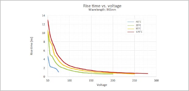
For LiDAR Systems, the rise times of APD pulses are key parameters for their performance. Therefore, the investigation of these parameters’ dependence on operating voltage and temperature is required. Figure 5 shows the rise time versus voltage for different temperatures. The rise time is determined by measuring with an oscilloscope the response upon excitation with ultrafast optical pulses. The measurement was done with an input impedance of 50 Ω. Figure 5 shows that for higher temperatures, a higher operating voltage is necessary to reach the same rise time. This causes a decreasing saturation drift speed for higher temperatures.
The results shown in Figure 5 show that lower temperatures improve dynamic behavior. Nevertheless, for many applications a fixed gain of an APD sensor is important. Figure 2 shows the gain curves for different temperatures. As mentioned before, lower temperatures cause steeper gain curves. This means the gain is very high, even for low voltages.
Rise Time and Dynamic Range
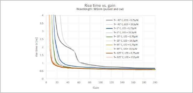
The mean free path of electrons in the multiplication volume is large and therefore the saturation drift speed is high. Nevertheless, the electric field is not high enough to compensate the positive effect of higher saturation drift speed. Figure 6 shows the rise time versus gain. For a certain gain, a higher temperature results in a shorter rise time. This is caused by a stronger electric field in the APD sensor for the same gain but at higher temperatures.
Figure 6 shows the influence of temperature on dynamic behavior for fixed multiplication and under simulation of continuous ambient light. Again, it can be observed that higher temperatures require higher operation bias for a certain gain causing faster responses. Also, it can be seen that stronger ambient illumination does not reduce response time or cause saturation. However, due to self-heating effects of CW photocurrent at -40° C, operation biases are slightly higher and therefore APDs seem faster under higher illumination densities.
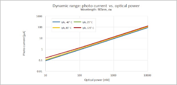
Figure 7 shows the photo current for different levels of 905nm CW illumination for different temperatures for a typical input range of a TIA. The dynamic range is not affected by the operating temperature between -40° C and 125° C.

CONCLUSION
This report introduces the importance of the temperature-dependent parameters of an APD sensor. It shows that desired APD characteristics are preserved between -40° C and 125° C. Therefore, the TE Connectivity APDs optimized for 905nm are well suited for grade 1 temperature range operation. The data shows that the APD performs in the complete grade 1 temperature range from -40°C to 125° C.
Author:
Jona Kurpiers, Ph.D., TE Connectivity


