Trend Insight
Understanding RTDs
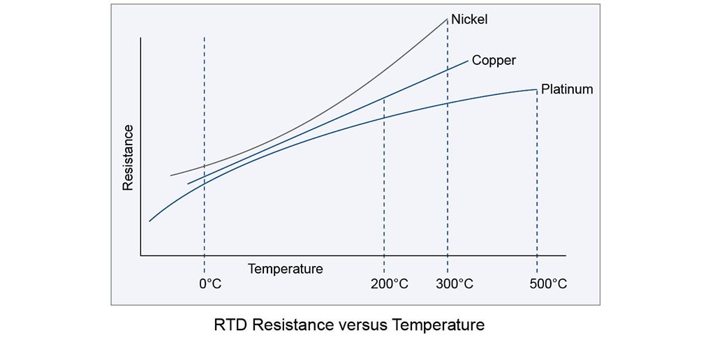
An RTD is a sensor whose resistance changes as its temperature changes.
Understanding RTDs
An RTD (Resistance Temperature Detector) is a sensor whose resistance changes as its temperature changes. The resistance increases as the temperature of the sensor increases. The resistance vs temperature relationship is well known and is repeatable over time. An RTD is a passive device. It does not produce an output on its own. External electronic devices are used to measure the resistance of the sensor by passing a small electrical current through the sensor to generate a voltage. Typically 1 mA or less measuring current, 5 mA maximum without the risk of self-heating.
Standard Tolerances
RTDs are built to several standardized curves and tolerances. The most common standardized curve is the ‘DIN’ curve. The curve describes the resistance vs temperature characteristics of a Platinum, 100 ohm sensor, the standardized tolerances, and the measurable temperature range.
The DIN standard specifies a base resistance of 100 ohms at 0°C, and a temperature coefficient of .00385 Ohm/Ohm/°C. The nominal output of a DIN RTD sensor is shown below:
There are three standard tolerance classes for DIN RTDs. These tolerances are defined as follows:
DIN Class A: ±(0.15 + .002 |T|°C)
DIN Class B: ±(0.3 + .005 |T|°C)
DIN Class C: ±(1.2 + .005 |T|°C)
| 0°C |
Ohms |
| 0 | 100.00 |
| 10 | 103.90 |
| 20 | 107.79 |
| 30 | 111.67 |
| 40 | 115.54 |
| 50 | 119.40 |
| 60 | 123.24 |
| 70 | 127.07 |
| 80 | 130.89 |
| 90 | 134.70 |
| 100 | 138.50 |
RTD Element Types
When deciding the RTD element type, first consider what instrument you will be reading the sensor with. Choose an element type that is compatible with the instrument’s sensor input. By far the most common RTDs are 100 Ohm Platinum with .00385 temperature coefficient.
| Element Type | Base Resistance in Ohms | TCR (Ohm/Ohm/°C) |
| Platinum | 100 Ohms at 0°C | .00385 |
| Platinum | 100 Ohms at 0°C | .00392 |
| Platinum | 100 Ohms at 0°C | .00375 |
| Nickel | 120 Ohms at 0°C | .00672 |
| Copper | 10 Ohms at 25°C | .00427 |

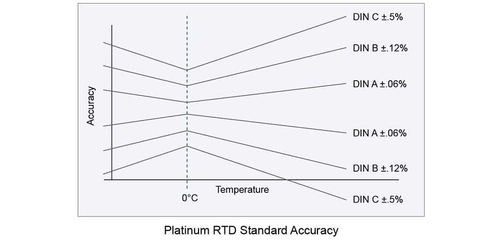
RTD Accuracy
Secondly, decide what accuracy is needed in your measurement. Accuracy is a combination of both base resistance tolerance (resistance tolerance at the calibration temperature) and temperature coefficient of resistance tolerance (tolerance in the characteristic slope). Any temperature above or below this temperature will have a wider tolerance band or less accuracy (see graph below). The most common calibration temperature is 0°C.
Sensor Connections
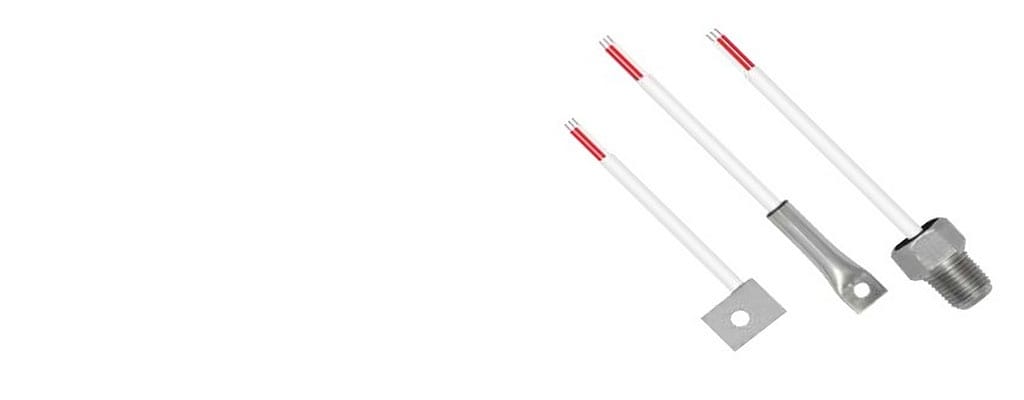
RTD Sensors are available in a number of different lead wire configurations. The most common configuration is the single element, three lead configuration. Schematics of the available lead wire configurations are shown below:
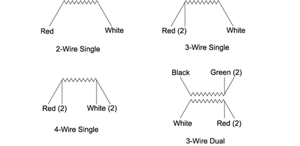
Two wire sensors are typically used in applications where accuracy is not critical. The two wire configuration allows for the simplest measurement technique, but suffers from an inherent inaccuracy due to the resistance of the sensor leads. In the two wire configuration, there is no way to directly compensate for the resistance of the lead wires which will cause an offset increase in the resistance measurement.
Three wire sensors are built with a compensation loop to allow the measurement to factor out the resistance of the leads. With this configuration, the controller/measurement device makes two measurements. The first measurement measures the total resistance of the sensor and the connecting lead wires. The second measurement is the resistance of the compensation loop resistance. By subtracting the compensation loop resistance from the total resistance, an account net resistance is determined. Three wire sensors are the most common and give a good combination of accuracy and convenience.
The four wire sensor configuration and measurement techniques allow measurement of the sensor resistance without the influence of the lead wires. While this technique gives the best accuracy, many industrial controllers/measurement devices cannot make a true four wire measurement.
The transition from the sensor lead wires to the field wiring is typically done in a connection head attached to the sensor. Terminal blocks are used to facilitate the connection.
Lead Wire Effects
Measurement of temperature with a resistance temperature detector is a matter of measuring resistance. Unbalanced Wheatstone bridges are invariably used to measure the resistance. When measuring the resistance of the sensing element, all external factors must be minimized or compensated for, in order to obtain an accurate reading.
A major cause of error can be the resistance of the lead wires, especially in two lead configurations.
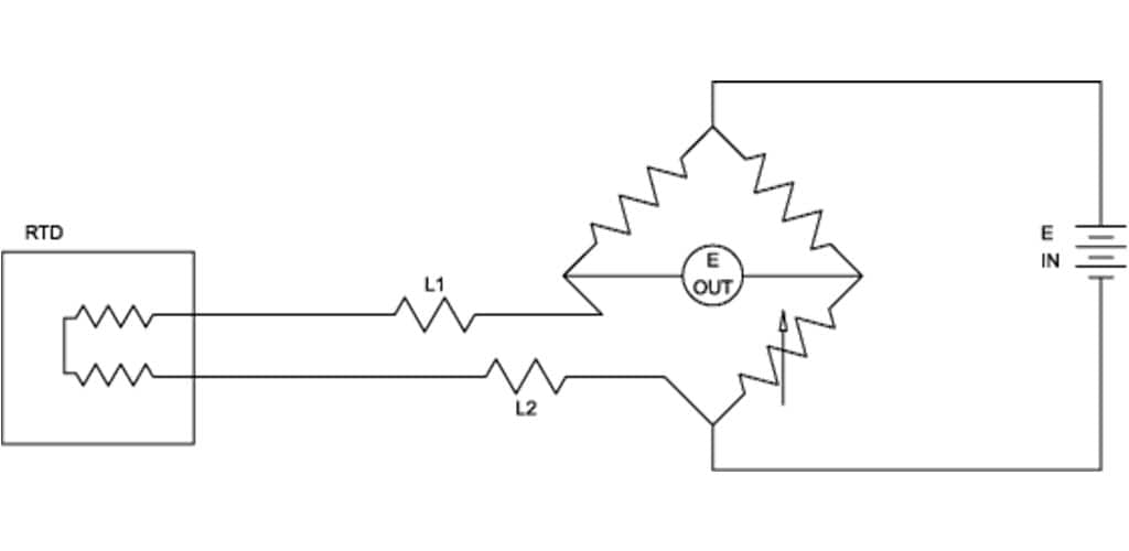
The resistance is in series with the sensing element, so the readout is the sum of the resistances of the sensing element and the lead wires. Two-lead RTDs are possible when the sensing element has a high resistance and the lead wires have a low resistance.
When the lead wire resistance is comparably high, however, it must be compensated. Compensation can be achieved with a three-lead configuration. As shown in the three-lead diagram, one side of the power supply is taken to one side of the RTD via L3. This puts L1 and L2 in opposite arms of the bridge so they cancel each other out and have no effect on the bridge output voltage.
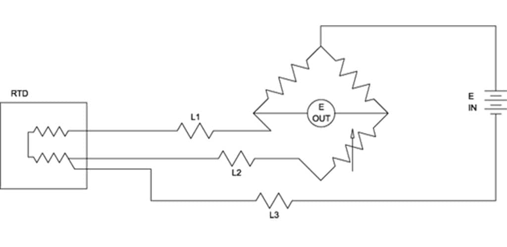
Three-lead connections are recommended for RTDs, especially with low sensing element resistance, where a small lead wire resistance can have a large effect on readout accuracy.
EXPLORE MORE TEMPERATURE SENSOR RESOURCES