Analysis of Linear Electromagnetic Actuator using FEA
ABSTRACT
In this paper, we analyzed the dynamic characteristics of an electromagnetic actuator, used for vacuum circuit breakers. The magnetic, electrical, and mechanical phenomena are simultaneously analyzed to obtain the dynamic behavior of the actuator. The magnetic parameters are computed by using the finite element analysis (FEA) and then are imported to dynamic analysis software, where the electric and mechanical equations are calculated. The results of the analysis along with some experimental data are presented. This technique can be used for analyzing in a very accurate way the dynamic electromagnetic behavior of sensors, relays, switches, and other actuator systems.
PROBLEM STATEMENT
The electromagnetic actuator is widely used in circuit breakers. Its role is to achieve movement of the movable contacts of the vacuum bottle with certain speeds and precise trajectories.
In this report, a novel model of a linear actuator, which will be used in the new generation of the TE rolling stock roofline systems, is proposed and analyzed. One factor which significantly affects the operation of the actuator is the magnetic drag force. This force could be due to:
- Static magnetic field: as the armature moves, it experiences magnetic pull (due to the relative movement with the magnets depending on their position).
- Residual coil current: when the holding voltage is disconnected from the coil, it takes time for the coil current to decay to zero. While present, it produces magnetic pull towards the closing position. Rapid current decay can be achieved by:
o Increasing TVS (Transient Voltage Suppressor) voltage
o Decreasing coil inductance
- Induced eddy currents [1]
- Movement induced eddy currents: this effect accounts for the most of the energy losses (if there is a relative movement between the armature and the magnets) and can be effectively reduced or even eliminated by moving the magnets in the armature (and / or using magnets with decreased magnetic field strength) [1].
- Back EMF (Electromotive Force) current: moving armature causes back EMF voltage which in turn causes back EMF current which acts against movement.
Previous research does not account for the effect of the eddy currents in the movement of the actuator armature, but, as it is critical for the performance of the actuator, all the above-mentioned effects have been taken into consideration, calculated and included in the model. Thus, our model predicts with high accuracy the real behavior of the actuator before prototyping and can be used for sensitivity analysis to reduce time for design and cost, providing an optimal technical and economical solution. More detailed description of the methods and results will follow in the next sections.
METHODS AND RESULTS
Static analysis
Fig. 1 shows the proposed structure of the electromagnetic actuator:
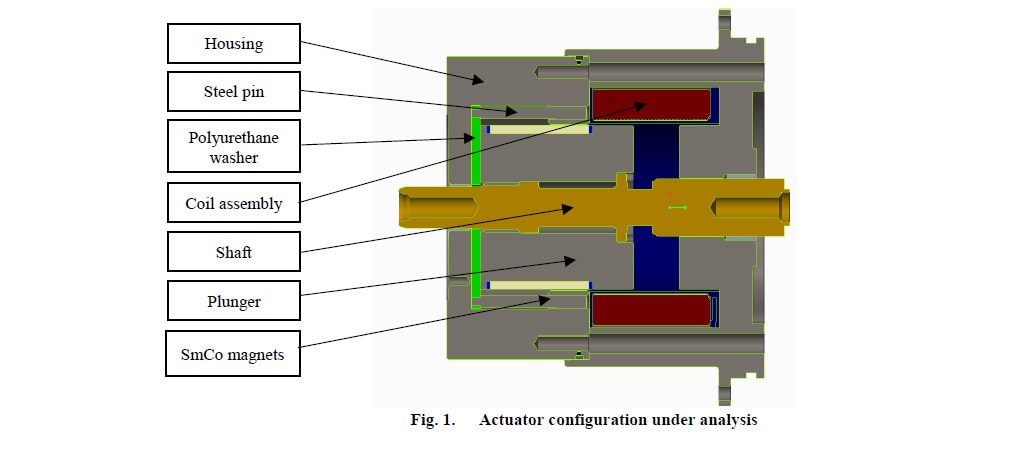
In comparison to a typical actuator (which usually consists of an opening and a closing coil), this type of actuator consists of the housing (or frame), the steel pin, the coil assembly (coil and bobbin), the armature (plunger), the shaft, the polyurethane washer and the permanent SmCo (Samarium Cobalt) magnets (PM).
The coil windings create an electromagnetic field when the current is applied across its terminals. The purpose of the coil is to drive the armature in the close position and help holding it there. This actuator should fail – safe (open) in the event of loss of power in the coil. The opening process begins when the current in the coil is cut off and is achieved only by
mechanical means (springs etc.). Thus, the power dissipation (critical for modern trains) in this type of actuator is significantly lower than the dissipation in a typical actuator, while safety is priority.
The stator concentrates the magnetic field. It surrounds the outside of the coil and is made of Low Carbon Steel AISI (American Iron and Steel Institute) 1018. Low Carbon Steel is used for most of electromagnetic actuators. It has a high permeability and a relative low cost [12].
The magnets are producing a holding force, which depends on the position of the armature relative to the housing (low and high magnetic reluctance).
For the analysis, the magnetic fields physics has been selected. To define the non – linear magnetic properties of the carbon steel and the remanent flux density of the magnets, Ampere’s Law has been applied to the relevant domains. The non – linear magnetic properties are introduced to account for magnetic saturation (the state when the magnetization of a
material reaches a point where it cannot increase further due to the increase of the applied external magnetic field H) [2] [3].
For the calculation of the electromagnetic force in the armature, the method of the Maxwell Stress Tensor has been applied. This tensor is mathematically an integral along a closed path (in 2D) or a closed surface area “A” (in 3D) around a domain of interest. One of the limitations of this method is that, when there is a magnetic material to magnetic material interface (acting as poles), a very small air gap (< 0.1mm) must be maintained between them, otherwise a very low value of the force is calculated, which does not correspond to its real value [12] [5].
Dynamic analysis
To study the dynamic behavior of the actuator two models have been simulated to account for its opening and closing performance [4] [7] [8]. The electric circuit used to drive the actuator is shown below (Fig.2):

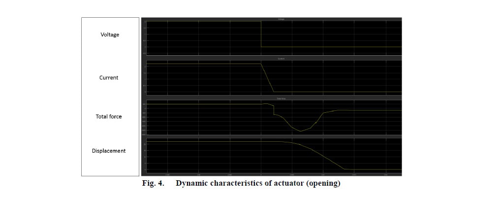
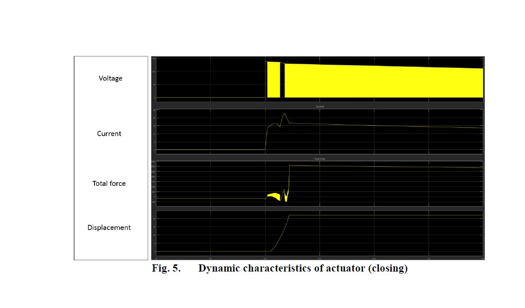
During opening, the current in the coil is cut off and the TVS is used to suppress the induced voltage (and consequently the induced current). During closing, a pulse sequence from the APS (actuator power source) is used to drive the actuator.
The equations solved ((1) – (3)) are as follows:

V: voltage (V), i: current (A), R: resistance (Ω), L: inductance (H), VEMF: back EMF voltage (V), v: velocity (m/s), α: acceleration (m/s2), t: time (s)ΣF: total force (N), M: mass (kg), Ψ: flux linkage (Wb-T). The flux linkages have two components one dependent of the magnetic field produced by the PM (BPM)and another component due to the magnetic field produced by the coil (Bc).
The eddy currents were calculated using the following equation [1]:

Where K1 is a geometric factor, l is the length of the plunger and ρ is the material resistivity [1]. Assuming the plunger as a cylinder equation 4 becomes:

The magnetic field produced by the eddy currents (Be) and the corresponding force (Fe)were calculated using equations 6 and 7.

Where lm is the magnetic path, r is the radius of the plunger and μ the material permittivity.
Simulation results
The magnetic field distribution at different positions is shown in Fig. 3.
In the close position (Fig. 3a), the armature along with the steel housing forms a path of low magnetic reluctance, while the large gap at the top represents a high magnetic resistance path. Therefore, the magnetic field lines run almost exclusively through the end of the armature being in contact with the housing. The holding force produced by the magnets in this
position is of high value. To achieve a fail-safe operation, the coil is also used to produce an even higher holding force to hold the armature in the close position.
To open, the current flowing through the coil is cut-off and the armature starts moving. As the armature moves from close to open position, the magnetic field lines are pushed towards the previously lower path (Fig. 3b) as now the air gap in the open position is getting smaller and smaller (the magnetic reluctance is getting lower). Therefore, the holding force at the bottom decreases, while the attraction at the top increases.
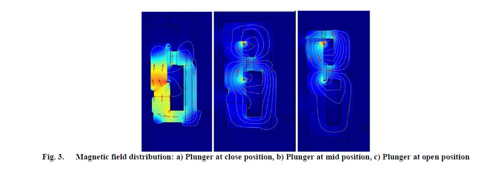
When the armature reaches the open position (Fig. 3c), the reluctance path is opposite than mentioned before, so the magnetic field lines are mostly concentrated at the top. As shown, the magnetic field concentration is not similar when the armature is in close and in open position. Therefore, the holding force at the open position will have a lower value than the one in the close position. The results of the dynamic analysis are shown in Fig. 4 and 5:
Some preliminary experimental results (Fig. 6 and 7) in slightly different actuator models (designs before final adgustments) prove the concept of the proposed design and control circuit.
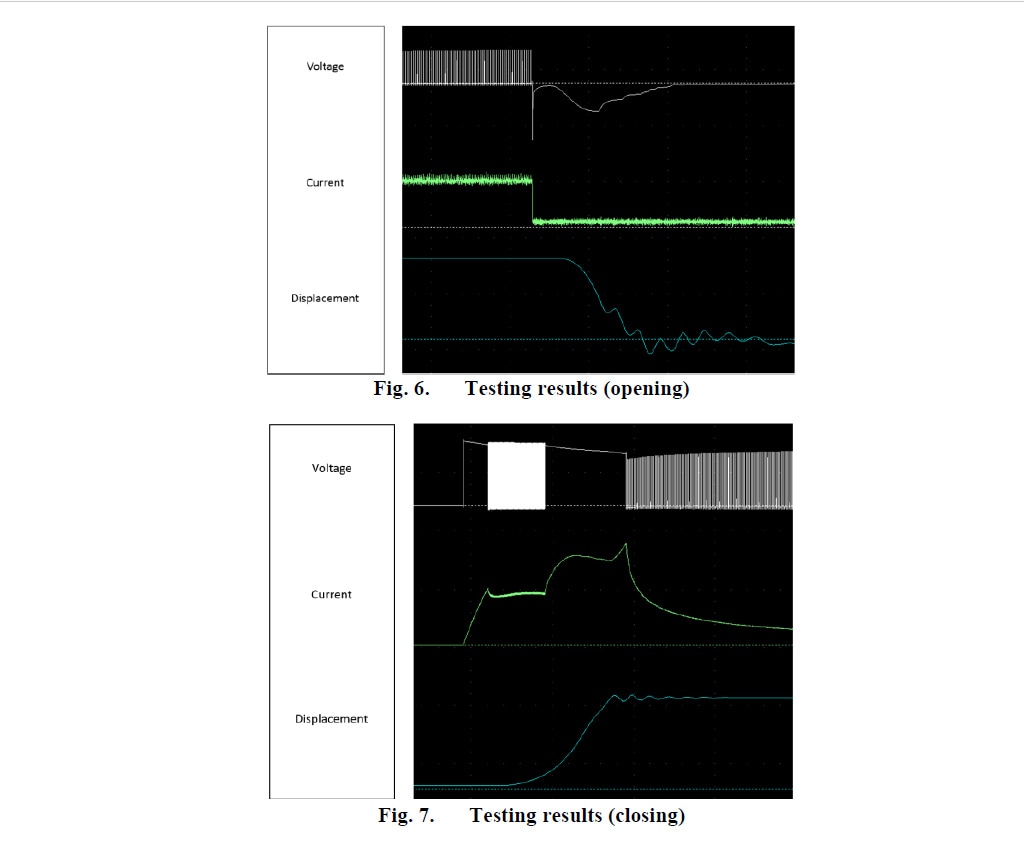
The profile of the dynamic characteristics observed during testing comes in agreement with the simulation results. The values of the speed and the duration of the closing and opening operation are similar in testing and simulations (less that 10% error).
DISCUSSION AND KEY POINTS
The optimised model of the actuator is proposed to minimize or even eliminate the effect of the electromagnetic braking due to induction. A novel control circuit is used to suppress this effect during opening, while, during closing, a pulsing sequence is introduced to control the performance of the actuator.
The innovative actuator design and the control circuit which improves the efficiency and performance of the system (low power dissipation) contribute significantly to the ongoing development of the new generation of TE train roofline systems. The actuator is designed to achieve reliable operation and conforms with the market’s low profile and lightweight
requirements (improving the aerodynamic performance) and the minimum power consumption.
Based on the comparison between testing and simulation results, it is concluded that the proposed calculation method can accurately analyse the transient characteristics of an electromagnetic actuator, while it is noteworthy to mention that the eddy current contribution is considered in this report, which is not the fact in most of the existing papers due to its
complicated form. Therefore, the importance of this method is that it can be used prior to prototyping to significantly reduce time, cost and resources during design and manufacturing.
ACKNOWLEDGEMENTS
We want to thank Graham Mcdonald and Robert Phillpotts for all the support and expert advice throughout this project. They provided the mechanical models and the electronics configurations following the recommendations from the analysis and the data for the mechanical forces.
REFERENCES
[1] Mandache, L.; D. Topan; K. Al Haddad. “Modeling of Non-Linear Ferromagnetic Cores”. Revue Roumaine de Sciences Techniques. Serie Electrotechnique et Energetique. Vol. 53, Issue 4. 2008.
[2] K. Srairi and M. Feliachi, “Numerical Coupling Moldels for Analyzing Dynamic Behaviors of Electromagnretic actuators,” IEEE Transactions on Magnetics, vol. 34, no. 5, pp. 3608-3611, 1998.
[3] I. Yatchev, V. Gueorgiev, K. Hinov, R. Ivanov and D. Dimitrov, “Dynamic characteristics of a permanent magnet electromagnetic valve actuator,” in 12th International Conference on Optimization of Electrical and Electronic Equipment, 2010.
[4] I. Yatchev, V. Gueorgiev, R. Ivanov and K. Hinov, “Simulation of the Dynamic Behaviour of a Permanent Magnet Linear Actuator,” Elec. Energ., vol. 23, no. 1, pp. 37-43, 2010.
[5] I. Yatchev and E. Ritchie, “Simulation of Dynamics of a Permanent Manget Linear Actuator,” Internation Journal of Mathematical, Computational, Physical, Electrical and Computer Engineering, vol. 4, no. 6, pp. 726-730, 2010.
[6] S.-M. Wang, T. Miyano and M. Hubbard, “Electromagnetic Field Analysis and Dynamic Simulation of a Two-Valve Actuator” IEEE Transactions on Magnetics, vol. 29, no. 2, pp. 1741-1746, 1993.
[7] A. Radulian and N. Mocioi, “Numerical Modelling of an Electromagnetic Actuator for Vacuum Contactors”. International Conference and Exposition on Electrical and Power Engineering, Iasi, Romania, 2014.
[8] N. Paudel, “Part 1: How to Model a Linear Electromagnetic Plunger,” 7th June 2016. [Online]. Available: https://www.comsol.co.in/blogs/part-1-how-to-model-a-linear-electromagnetic-plunger/.
[9] N. Paudel, “Part 2: Model a Linear Electromagnetic Plunger with a Blocker,” 14th June 2016. [Online]. Available: https://www.comsol.co.in/blogs/part-2-model-a-linear-electromagnetic-plunger-with-a-blocker/.
[10] D. Mayer and B. Ulrych, “Electromechanical Actuators Dynamics” J. of Electrical Engineering, vol. 60, no. 5, pp. 255, 2009.
[11] H. Musaab, “Using Look-up Tables to Model an Electromagnetic Suspansion System,” American Journal of Applied Sciences , vol. 9, no. 8, pp. 1199-1202, 2012.
[12] O. Vogel and J. Ulm, “Theory of Proportional Solenoids and Magnetic Force Calculation using Comsol Multiphysics,” in Comsol Conference, Stuttgart, 2011.
Analysis of Linear Electromagnetic Actuator using FEA
ABSTRACT
In this paper, we analyzed the dynamic characteristics of an electromagnetic actuator, used for vacuum circuit breakers. The magnetic, electrical, and mechanical phenomena are simultaneously analyzed to obtain the dynamic behavior of the actuator. The magnetic parameters are computed by using the finite element analysis (FEA) and then are imported to dynamic analysis software, where the electric and mechanical equations are calculated. The results of the analysis along with some experimental data are presented. This technique can be used for analyzing in a very accurate way the dynamic electromagnetic behavior of sensors, relays, switches, and other actuator systems.
PROBLEM STATEMENT
The electromagnetic actuator is widely used in circuit breakers. Its role is to achieve movement of the movable contacts of the vacuum bottle with certain speeds and precise trajectories.
In this report, a novel model of a linear actuator, which will be used in the new generation of the TE rolling stock roofline systems, is proposed and analyzed. One factor which significantly affects the operation of the actuator is the magnetic drag force. This force could be due to:
- Static magnetic field: as the armature moves, it experiences magnetic pull (due to the relative movement with the magnets depending on their position).
- Residual coil current: when the holding voltage is disconnected from the coil, it takes time for the coil current to decay to zero. While present, it produces magnetic pull towards the closing position. Rapid current decay can be achieved by:
o Increasing TVS (Transient Voltage Suppressor) voltage
o Decreasing coil inductance
- Induced eddy currents [1]
- Movement induced eddy currents: this effect accounts for the most of the energy losses (if there is a relative movement between the armature and the magnets) and can be effectively reduced or even eliminated by moving the magnets in the armature (and / or using magnets with decreased magnetic field strength) [1].
- Back EMF (Electromotive Force) current: moving armature causes back EMF voltage which in turn causes back EMF current which acts against movement.
Previous research does not account for the effect of the eddy currents in the movement of the actuator armature, but, as it is critical for the performance of the actuator, all the above-mentioned effects have been taken into consideration, calculated and included in the model. Thus, our model predicts with high accuracy the real behavior of the actuator before prototyping and can be used for sensitivity analysis to reduce time for design and cost, providing an optimal technical and economical solution. More detailed description of the methods and results will follow in the next sections.
METHODS AND RESULTS
Static analysis
Fig. 1 shows the proposed structure of the electromagnetic actuator:

In comparison to a typical actuator (which usually consists of an opening and a closing coil), this type of actuator consists of the housing (or frame), the steel pin, the coil assembly (coil and bobbin), the armature (plunger), the shaft, the polyurethane washer and the permanent SmCo (Samarium Cobalt) magnets (PM).
The coil windings create an electromagnetic field when the current is applied across its terminals. The purpose of the coil is to drive the armature in the close position and help holding it there. This actuator should fail – safe (open) in the event of loss of power in the coil. The opening process begins when the current in the coil is cut off and is achieved only by
mechanical means (springs etc.). Thus, the power dissipation (critical for modern trains) in this type of actuator is significantly lower than the dissipation in a typical actuator, while safety is priority.
The stator concentrates the magnetic field. It surrounds the outside of the coil and is made of Low Carbon Steel AISI (American Iron and Steel Institute) 1018. Low Carbon Steel is used for most of electromagnetic actuators. It has a high permeability and a relative low cost [12].
The magnets are producing a holding force, which depends on the position of the armature relative to the housing (low and high magnetic reluctance).
For the analysis, the magnetic fields physics has been selected. To define the non – linear magnetic properties of the carbon steel and the remanent flux density of the magnets, Ampere’s Law has been applied to the relevant domains. The non – linear magnetic properties are introduced to account for magnetic saturation (the state when the magnetization of a
material reaches a point where it cannot increase further due to the increase of the applied external magnetic field H) [2] [3].
For the calculation of the electromagnetic force in the armature, the method of the Maxwell Stress Tensor has been applied. This tensor is mathematically an integral along a closed path (in 2D) or a closed surface area “A” (in 3D) around a domain of interest. One of the limitations of this method is that, when there is a magnetic material to magnetic material interface (acting as poles), a very small air gap (< 0.1mm) must be maintained between them, otherwise a very low value of the force is calculated, which does not correspond to its real value [12] [5].
Dynamic analysis
To study the dynamic behavior of the actuator two models have been simulated to account for its opening and closing performance [4] [7] [8]. The electric circuit used to drive the actuator is shown below (Fig.2):

During opening, the current in the coil is cut off and the TVS is used to suppress the induced voltage (and consequently the induced current). During closing, a pulse sequence from the APS (actuator power source) is used to drive the actuator.
The equations solved ((1) – (3)) are as follows:

V: voltage (V), i: current (A), R: resistance (Ω), L: inductance (H), VEMF: back EMF voltage (V), v: velocity (m/s), α: acceleration (m/s2), t: time (s)ΣF: total force (N), M: mass (kg), Ψ: flux linkage (Wb-T). The flux linkages have two components one dependent of the magnetic field produced by the PM (BPM)and another component due to the magnetic field produced by the coil (Bc).
The eddy currents were calculated using the following equation [1]:

Where K1 is a geometric factor, l is the length of the plunger and ρ is the material resistivity [1]. Assuming the plunger as a cylinder equation 4 becomes:

The magnetic field produced by the eddy currents (Be) and the corresponding force (Fe)were calculated using equations 6 and 7.

Where lm is the magnetic path, r is the radius of the plunger and μ the material permittivity.
Simulation results
The magnetic field distribution at different positions is shown in Fig. 3.
In the close position (Fig. 3a), the armature along with the steel housing forms a path of low magnetic reluctance, while the large gap at the top represents a high magnetic resistance path. Therefore, the magnetic field lines run almost exclusively through the end of the armature being in contact with the housing. The holding force produced by the magnets in this
position is of high value. To achieve a fail-safe operation, the coil is also used to produce an even higher holding force to hold the armature in the close position.
To open, the current flowing through the coil is cut-off and the armature starts moving. As the armature moves from close to open position, the magnetic field lines are pushed towards the previously lower path (Fig. 3b) as now the air gap in the open position is getting smaller and smaller (the magnetic reluctance is getting lower). Therefore, the holding force at the bottom decreases, while the attraction at the top increases.

When the armature reaches the open position (Fig. 3c), the reluctance path is opposite than mentioned before, so the magnetic field lines are mostly concentrated at the top. As shown, the magnetic field concentration is not similar when the armature is in close and in open position. Therefore, the holding force at the open position will have a lower value than the one in the close position. The results of the dynamic analysis are shown in Fig. 4 and 5:


Some preliminary experimental results (Fig. 6 and 7) in slightly different actuator models (designs before final adgustments) prove the concept of the proposed design and control circuit.

The profile of the dynamic characteristics observed during testing comes in agreement with the simulation results. The values of the speed and the duration of the closing and opening operation are similar in testing and simulations (less that 10% error).
DISCUSSION AND KEY POINTS
The optimised model of the actuator is proposed to minimize or even eliminate the effect of the electromagnetic braking due to induction. A novel control circuit is used to suppress this effect during opening, while, during closing, a pulsing sequence is introduced to control the performance of the actuator.
The innovative actuator design and the control circuit which improves the efficiency and performance of the system (low power dissipation) contribute significantly to the ongoing development of the new generation of TE train roofline systems. The actuator is designed to achieve reliable operation and conforms with the market’s low profile and lightweight
requirements (improving the aerodynamic performance) and the minimum power consumption.
Based on the comparison between testing and simulation results, it is concluded that the proposed calculation method can accurately analyse the transient characteristics of an electromagnetic actuator, while it is noteworthy to mention that the eddy current contribution is considered in this report, which is not the fact in most of the existing papers due to its
complicated form. Therefore, the importance of this method is that it can be used prior to prototyping to significantly reduce time, cost and resources during design and manufacturing.
ACKNOWLEDGEMENTS
We want to thank Graham Mcdonald and Robert Phillpotts for all the support and expert advice throughout this project. They provided the mechanical models and the electronics configurations following the recommendations from the analysis and the data for the mechanical forces.
REFERENCES
[1] Mandache, L.; D. Topan; K. Al Haddad. “Modeling of Non-Linear Ferromagnetic Cores”. Revue Roumaine de Sciences Techniques. Serie Electrotechnique et Energetique. Vol. 53, Issue 4. 2008.
[2] K. Srairi and M. Feliachi, “Numerical Coupling Moldels for Analyzing Dynamic Behaviors of Electromagnretic actuators,” IEEE Transactions on Magnetics, vol. 34, no. 5, pp. 3608-3611, 1998.
[3] I. Yatchev, V. Gueorgiev, K. Hinov, R. Ivanov and D. Dimitrov, “Dynamic characteristics of a permanent magnet electromagnetic valve actuator,” in 12th International Conference on Optimization of Electrical and Electronic Equipment, 2010.
[4] I. Yatchev, V. Gueorgiev, R. Ivanov and K. Hinov, “Simulation of the Dynamic Behaviour of a Permanent Magnet Linear Actuator,” Elec. Energ., vol. 23, no. 1, pp. 37-43, 2010.
[5] I. Yatchev and E. Ritchie, “Simulation of Dynamics of a Permanent Manget Linear Actuator,” Internation Journal of Mathematical, Computational, Physical, Electrical and Computer Engineering, vol. 4, no. 6, pp. 726-730, 2010.
[6] S.-M. Wang, T. Miyano and M. Hubbard, “Electromagnetic Field Analysis and Dynamic Simulation of a Two-Valve Actuator” IEEE Transactions on Magnetics, vol. 29, no. 2, pp. 1741-1746, 1993.
[7] A. Radulian and N. Mocioi, “Numerical Modelling of an Electromagnetic Actuator for Vacuum Contactors”. International Conference and Exposition on Electrical and Power Engineering, Iasi, Romania, 2014.
[8] N. Paudel, “Part 1: How to Model a Linear Electromagnetic Plunger,” 7th June 2016. [Online]. Available: https://www.comsol.co.in/blogs/part-1-how-to-model-a-linear-electromagnetic-plunger/.
[9] N. Paudel, “Part 2: Model a Linear Electromagnetic Plunger with a Blocker,” 14th June 2016. [Online]. Available: https://www.comsol.co.in/blogs/part-2-model-a-linear-electromagnetic-plunger-with-a-blocker/.
[10] D. Mayer and B. Ulrych, “Electromechanical Actuators Dynamics” J. of Electrical Engineering, vol. 60, no. 5, pp. 255, 2009.
[11] H. Musaab, “Using Look-up Tables to Model an Electromagnetic Suspansion System,” American Journal of Applied Sciences , vol. 9, no. 8, pp. 1199-1202, 2012.
[12] O. Vogel and J. Ulm, “Theory of Proportional Solenoids and Magnetic Force Calculation using Comsol Multiphysics,” in Comsol Conference, Stuttgart, 2011.
