White Paper
Sensor Fusion in Tilt Sensors
Learn how sensor fusion plays a vital role in the new generation of tilt sensors.
INTRODUCTION
An inclination or tilt sensor provides angular tilt information relative to gravitational force. This information can be used to monitor the status of equipment or can be used to control the characteristics of a device or vehicle. Different types of sensors are used in different applications as well. Inexpensive, surface mount tilt sensors are becoming more and more popular in handheld technology. They are used to monitor the angle at which a phone is held for the auto-rotate function. Another example is the use of tilt sensors in gaming consoles.
Ruggedized tilt sensors are used in a wide range of industrial machinery as well a range of on and off-road vehicles and construction equipment. These sensors are used for a variety of functions including ride control, cabin leveling, boom angle measurement as well as tip over protection. Safety requirements are being added in a range of vehicles and construction equipment that require sensors to monitor the tilt or inclination to ensure the safety of the operator and those nearby.
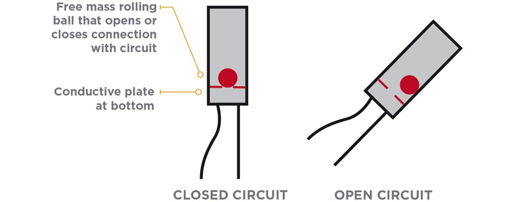
The technology for tilt or inclination sensors has evolved over the years from simple tilt switches to sophisticated fully electronic sensors that combine multiple sensing technologies. Many years ago, these devices were not sensors but switches that consisted of a rolling ball with conductive plate underneath. The switches were designed such that a sufficient level of tilt would allow the ball to roll to the bottom and form an electrical connection with the plate and that signal could be then be used either as an indicator or could be used to turn something on or off.
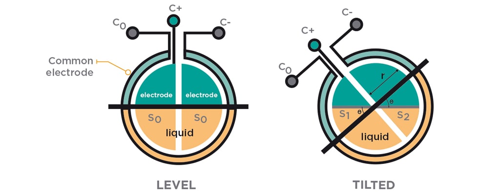
Early tilt sensors contained resistive or capacitive liquids inside a sealed cavity. As the capsule tilts end to end, the liquid flows to one side or the other which changes the resistance or capacitance of an internal circuit and the output of the circuit could be monitored directly, or the output could be amplified or translated into other output formats. While these sensors could provide accurate and reliable inclination data in many applications, they had several weaknesses including slow time response, susceptibility to vibration and sloshing and limited lifespans.
MODERN TILT OR INCLINATION SENSORS TYPICALLY USE MICROELECTROMECHANICAL SYSTEMS (MEMS) TECHNOLOGY.
Solid state MEMS are small sensors as they consist of movable proof mass plates that are attached to a reference frame through a mechanical suspension system. This is a technique of combining mechanical and electrical components together on a chip to generate a system with miniature dimensions. For a MEMS-based tilt sensor, a mass is added to sensor silicon die. In the horizontal position, the force of gravity deflects the die (like the application of pressure) and produces an electrical output. As the die is rotated to the vertical position, the force on the die goes to zero, as does the electrical output. The output is a 16-bit two’s complement number that represents the tilt angle in degrees. MEMS-based tilt sensor solved many of the issues with liquid-based technologies.
The function and accuracy of a tilt sensor is affected by many factors. Some of these factors are gravity, temperature, calibration of the tilt sensor, linearity, and cross-axis sensitivity. Some of the key specifications of a tilt sensor:
- Number of axes: The number of axes is an important factor as it varies from application to application. In robotics, a dual axis tilt sensor is used. In video game controllers and joysticks, a three-axis tilt sensor is required. In some smartphones, four-axis sensors are used.
- Resolution: The minimum inclination detected and output by the sensor
- Measuring range: The range of inclination that can be handled by the sensor. Some sensors are capable of measurements of only 10° while others can cover a range of up to 60°, 75° or even 90°.
- Noise tolerance: Noise tends to cause harmonic distortions in the function of the sensor, resulting in output variation and a reduction of system efficiency.
- Vibration and shocks: Vibrations can disrupt the sensor’s functionality, and hence vibration resistance measures are required, especially when the sensors are used in harsh conditions; for example, in off-road vehicles or construction sites’

Also, it is important to differentiate between (quasi) static and dynamic applications. In a dynamic application, the sensor is influenced by additional acceleration, while in static or slow-motion applications these can typically be neglected. For static tilt sensing, commonly used sensing technologies are based strictly on gravity, for example
- accelerometers, today usually MEMS type
- liquid filled elements, conductive or non-conductive with electronic readout
- convection cavity with heater
- pendulum with encoder or potentiometer
Static condition means the vehicle is not moving or the vehicle is moving at constant speed and direction or acceleration is very low. In other words, its trajectory is an ideal straight line, e.g. no potholes and no curves and also vibration is minimal.
Why is this important when using a tilt sensor? MEMS based tilt sensors utilize gravity as the acting force on the sense element. A typical approach for a MEMS tilt sensor would include a 3-axis accelerometer where gravity acts on each individual axis depending upon the tilt angle and the signals are temperature compensated and linearized and the actual tilt angle is calculated from the 3D acceleration data. However, any additional acceleration, e.g. vehicle speed changes or a pothole (shock) or curve, leads to distortion of the calculated tilt because the accelerometer “sees” the additional acceleration. This is common to all gravity-based devices and can create large errors.
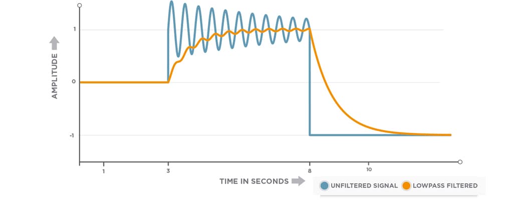
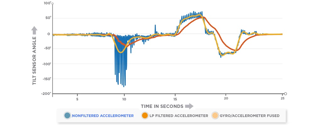
While TE Connectivity (TE) MEMS tilt sensors offer excellent accuracy better than ±0.15° at ambient temperature, additional acceleration can cause errors up to a few degrees. A common way to stabilize the output is to implement low pass filters. All TE tilt sensors make use of this. Moderate vibration and shocks are sufficiently damped this way, and, in many applications, this is enough and yields good results. The main drawback of using low pass filters is that it comes with a delay in the output and – due to its nature – the output cannot follow fast position changes. This may not be an issue but in some applications it is. In some applications it is necessary to have both, a cancellation of errors induced by shock and vibration on the one hand and an output that follows the true orientation of the vehicle on the other hand. A pure gravity-based sensor is not a solution in this case, no matter how it operates or what type of filtering or compensation is done.
SENSOR FUSION IS THE KEY
This means that information from different sensors are combined to calculate the output signal. A combination of an accelerometer and a gyroscope is a powerful approach. The weakness of the one sensor is compensated by the strength of the other one.
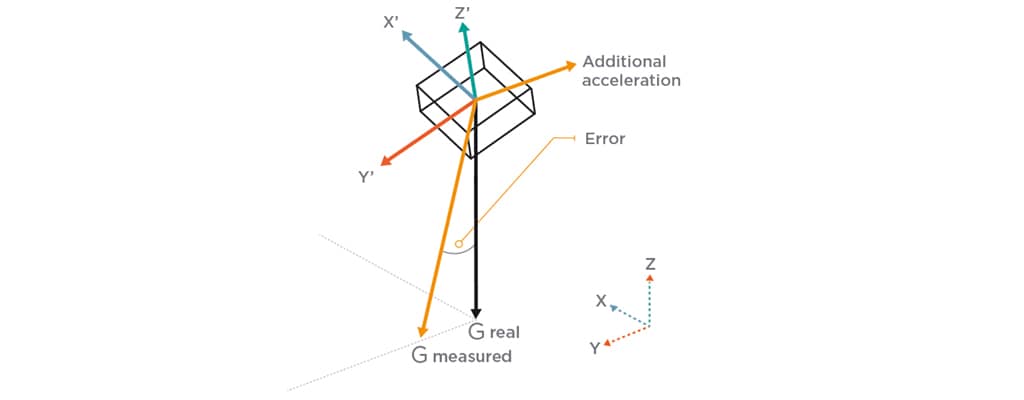
A gyro sensor measures rate of rotation or angular velocity around a particular axis. For example, in an aircraft a gyroscope can be used to measure the rate of rotation around the aircraft roll axis. The gyroscope would measure a non-zero value as long as the aircraft is rolling but indicates zero if the roll stops. This means, a roll gyroscope in an aircraft in a coordinated turn with a 60-degree bank measures a rate of zero, same as an aircraft flies straight and level. The current roll angle can be approximated by integrating the roll rate over time, but not without some error creeping in. Also, the gyroscope drifts over time, so additional errors will accumulate over a period of time, and eventually, you have an inaccurate idea of your current roll angle relative to the horizon. So, gyro-sensors alone cannot be used to keep an aircraft or any vehicle or piece of equipment in a particular orientation. So, for most dynamic applications you need both an accelerometer and a gyro to measure the inclination and to evaluate it correctly.
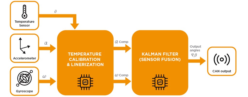
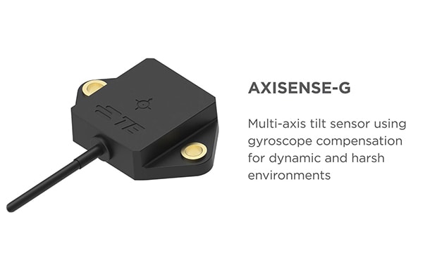
TE’s solution, the AXISENSE-G, is a gyro-stabilized tilt sensor that combines a 3-axis accelerometer, a gyroscope and a temperature sensor along with a sophisticated MCU and a CAN-bus interface all in one rugged and compact package. Algorithms take data from different sensors, compensate temperature effects and fuse them together to yield a stabilized but fast-tracking tilt output signal. There are different ways of implementing a fusion of sensor signals.
KALMAN FILTER
TE decided to use the well-known Kalman filter in an extended implementation to combine the sensor data and provide an accurate and reliable output under dynamic conditions for the AXISENSE-G tilt sensor. Kalman filtering, also known as linear quadratic estimation (LQE), is an algorithm that uses a series of measurements observed over time, containing statistical noise and other inaccuracies, and produces estimates of unknown variables that tend to be more accurate than those based on a single measurement alone, by estimating a joint probability distribution over the variables for each timeframe. The filter is named after Rudolf E. Kálmán, one of the primary developers of its theory.
THE BENEFITS
The main benefit of stabilizing a tilt sensor by using a gyroscope is that this clearly reduces the negative effect of additional short-term acceleration due to changes in speed or direction as well as bumps and vibration. Sometimes the term “IMU” (inertial measurement unit) is used when talking about fused position sensors. TE does not use this wording because it is usually used in the context of navigation, which comes with different requirements.
The AXISENSE-G tilt sensor is focusing on damping of short-term effects. As it does not need to use global position information, such as GPS data, the sensor is compact in size, easy to install easy to use, rugged and reliable and very cost competitive. Also, the TE AXISENSE-G tilt sensor can directly replace a standard TE tilt sensor without gyro because it has the same fit, form and function and utilizes the same CAN-Bus communication interface.
Summary
Tilt sensors technology has evolved over the years from simple mechanical designs to more sophisticated liquid-filled technologies that provided accurate and reliable inclination information over a wide range of angles and in more than one axis. MEMS technology allowed the further development and refinement of tilt sensors providing solid-state designs with increased accuracy and resolution as well as more rugged and reliable designs. Filtering and temperature compensation provided for more accurate tilt sensing in a broader range of applications as well as allowing their use in more dynamic applications. However, conventional tilt sensors do not always perform well enough in environments with heavy vibration and shocks. This problem is addressed by sensor fusion - fusing accelerometer and gyroscope data, resulting in a new generation of tilt sensors that remain responsive in dynamic conditions but are much less affected by acceleration generated in the application.

