eVTOL Systems Reveal New Opportunities for Rugged Fiber Optic Solutions
The technological needs and space constraints of eVTOL systems are markedly different from what’s required in most commercial aircraft, which presents new opportunities for rugged fiber optic (RFO) cables and connectors.
Connect with TE
Contact TE to discuss rugged fiber optic solutions for your next eVTOL project with one of our engineers.
eVTOL Systems Reveal New Opportunities for Rugged Fiber Optic Solutions
In the very near future, electric vertical take-off and landing (eVTOL) aircraft will offer new mobility options to carry cargo and passengers while also enabling emergency service providers to deliver enhanced fire, security, and search-and-rescue (SAR) services to the communities they serve. eVTOL aircraft operate at altitudes from 150 meters (500 feet) to 4 kilometers (2.5 miles) above the ground.
eVTOL systems present two key opportunities within the urban air mobility (UAM) market to better utilize airspace above and between population centers where traditional air travel is inefficient or impossible. First is local transportation within urban areas or between urban and suburban areas, a market that’s currently served by taxis, helicopters, ridesharing companies, or public transportation. Second is regional transport within a range of 150 to 250 kilometers (90-160 miles) that’s not being fully served by commercial airlines today.
By 2030, experts predict there will be thousands of eVTOL aircraft in operation and the UAM sector will grow to become more than a $1 trillion market by 2040. In the meantime, UAM industry groups, eVTOL platform manufacturers, and local regulators are moving quickly to engineer better aircraft, establish certification requirements, determine the supporting infrastructure, and develop eVTOL traffic management protocols.
eVTOL Challenges in Avionic System Design
All aircraft designers and manufacturers look for avionics components that add minimal weight to the aircraft while reducing the amount of space required for cabling and interconnects. However, the technological needs and space constraints of eVTOL applications are markedly different from what’s required in most commercial aircraft today, which presents new opportunities for rugged fiber optic (RFO) cables and connectors.
EMI protection: For commercial airplanes, controlling electromagnetic interference (EMI) is important so sensitive signals aren’t corrupted by other noise in the environment. But in eVTOL systems, the issue is slightly different. Critical control signals pass through areas with Direct Current (DC) to Alternating Current (AC) inverters, which creates a challenging environment that can add crosstalk and noise to copper cabling. The need for greater resistance to EMI and crosstalk can be solved with the use of RFO components in eVTOL aircraft.
Aircraft health monitoring: Rotor helicopters and other traditional platforms have Health Usage Monitoring Systems (HUMS) and Prognostic Health Management (PHM) systems that include arrays of sensors and data loggers to keep track of the vehicle’s structure, motor systems, drive components, and other critical parts of the craft. These systems collect significant amounts of data that are either used in real-time monitoring while in flight or downloaded at the end of each flight. This information must be gathered to certify the health of the vehicle for its next flight. If eVTOL platforms require similar HUMS and PHM systems, these systems will require additional cabling and assemblies that will impact weight limits and drive the use of advanced fiber optics for weight reduction.
Redundant systems: Certification requirements for eVTOL aircraft are still being defined. However, it is likely that these requirements will necessitate the inclusion of redundant systems that rely on different technologies so one failure mode doesn’t apply to both systems. As a result, a primary critical control system that contains copper components will have a backup system that relies on fiber optics or vice versa.
Ease-of-use and maintenance: There’s a misperception that optical fiber and fiber optic connectors are difficult to use and maintain. This may have been true when most fiber optic connections were terminated in the field. Today, most fiber optic cable assemblies and harnesses are built on production lines in controlled environments. Manufacturers can maintain cleanliness, test connections, and verify performance before the assembly is shipped to the end user and verified on the platform. Advanced fiber optic assemblies can be designed and built with the mechanisms needed to maintain cleanliness throughout installation and buildout of the complete aircraft.
Bandwidth: In commercial aircraft, rising demand for Wi-Fi access, streaming video, and in-flight entertainment is driving an increased need for more bandwidth to service hundreds of passengers on an aircraft’s network. In-flight entertainment is less of a concern for shorter, urban flights, and most eVTOL protocols for motor/rotor and flight controls call for low-speed 10BASE-T Ethernet or CANbus cables, so high-speed, high-bandwidth RFO solutions may not be necessary for some eVTOL systems. However, with their smaller form factor and the other advantages they deliver as compared to copper, rugged fiber optic solutions are better suited for most eVTOL aircraft applications.
Lightweight Fiber Optics Offer Advantage in eVTOL Aircraft
Reducing weight in battery-powered eVTOL aircraft typically translates into increased battery life, which can extend the aircraft range or help increase passenger load or payload. For every 150 kg (330 lbs) of weight savings, one more passenger can be added, or the range and flight time of the aircraft can be extended for existing passengers and/or cargo. Significant weight savings can be achieved with the implementation of rugged fiber optic technology.
Advanced fiber optic solutions typically weigh less and require less space than electrical equivalents. For example, switching from a Polyvinyl chloride (PVC) has context menu Cat 5 cable to a duplex fiber optic cable, which is typically used for an optical Ethernet link, can deliver upto 25% space savings and upto 50% reduction in weight. This is because the two types of cable have different constructions. The fiber option contains optical fibers, Kevlar® strength members, and the jacket material. On the electrical side, the Cat 5 cable has four twisted pairs, or eight strands of copper. There’s also copper shielding, which results in a larger diameter cable and adds weight to the overall assembly.
In a recent analysis, a 5-fiber optical cable was proposed for use in a control system for a new aircraft. For comparison, the 5-fiber cable was mapped one-to-one with an equivalent twisted pair cable using CANbus cable in two different wire gauges. The CANbus cable required 2.5 times as much cable and contributed up to 12 times more weight to make the same connections as the 5-fiber cable. The results are summarized below.
Weight Comparison: Fiber Optic Cable vs Copper Cable*
| Fiber Optic Cable 5 Fiber | CANbus 120 Ohm STP 26 AWG | CANbus 120 Ohm STP 24 AWG | |
| Total FO Cable Length (km) | 0.48 | 1.19 | 1.19 |
| Total Weight (kg) | 1.91 | 17.65 | 23.06 |
| Ratio | 1 | 9.30 | 12.10 |
| *2.5x total length in copper to provide 1:1 map of fiber optic signal paths | |||
In this example, the switch from copper to fiber optics reduces the weight of the cabling by a factor of 9 to 12 depending on the gauge of wire used. Apply that same potential weight savings to each cable assembly in the entire platform and the weight reduction becomes significant.
Rugged Fiber Optic Technology Meets the Unique Space and Volume Requirements of eVTOL Systems
Many of the proposed eVTOL airframe designs feature novel structural assemblies with tight constraints around space and volume. Physical contact and expanded beam connectors coupled with fiber optical flex circuits make it possible to design cable assemblies or interconnect systems that fit within limited available space.
Types of Rugged Fiber Optic Connectors
For decades, rugged fiber optic cables and connectors have been qualified, used, and maintained for commercial, military, and industry applications in the air, on the ground, above and under water, and in space. That experience has led to two proven options for fiber optic connections:
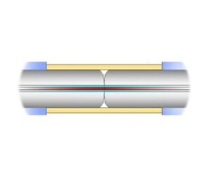
- Physical contact (PC) – Two, typically ceramic, ferrules are brought together under a spring force and aligned carefully to couple the light across the interface.
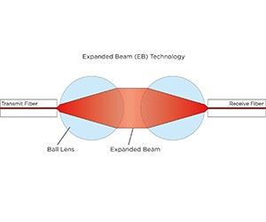
- Expanded beam (EB) – Two ferrules are drawn apart and lensing elements are inserted to create a collimating, free-space beam connection.


Comparing PC and EB Connector Technologies
There are advantages and disadvantages to each connector technology. The following table shows the relative merits of each option.
| Performance Criteria | PC | EB |
| Insertion Loss | **** | ** |
| Return Loss (SM) | **** | ** |
| Return Loss (SM) – Unmated | * | ** |
| Lateral Connector Misalignment | * | **** |
| Connector Angular Tilt | **** | * |
| Mating Durability | ** | **** |
| Water Exposure | *** | ** |
| Dust Exposure | * | *** |
| Vibration Susceptibility | ** | *** |
| Repair | ** | ** |
| Cleanability | ** | **** |
| Wear | * | **** |
| Wavelength Range | **** | ** |
Selecting the best type of connection will depend on where, why, and how the connector will be used. For example, if having the absolute best insertion loss is a priority, a PC will generally be better than an EB. However, EB functionality continues to improve and is closing the gap in terms of insertion loss as compared to PCs.
If the connection will need to be made and broken in the field repeatedly, keeping dust or debris out of the interface becomes paramount. This can occur with a connection to a data download port. In mating durability tests, where dust or dirt was allowed to enter the PC connector, the insertion loss was shown to degrade over time until a point at which the PC connector will need to be replaced. EBs are more expensive and initially deliver higher insertion loss performance as compared to PCs. But in the presence of dust, EBs deliver better mating durability and more consistent performance over the life of the connector.
Ultimately, the choice of which type of connector to use requires analysis for each performance criteria based on the type of optical traffic and wavelengths on the network, how the connector is going to be installed, the size and weight constraints of the design, and the harsh environments in which the eVTOL aircraft will be used.
Fiber Optical Flex Circuits
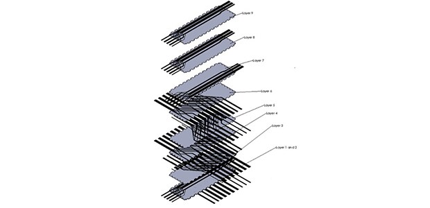
Fiber optical flex circuits are composed of multiple, individual fibers precisely positioned into a predetermined form or pattern and fixed in place using a special coating designed to bond the fibers together in position. In addition to organizing the interconnections among the various fibers in the system, fiber optical flex circuits provide easy routing and advanced management of thousands of fibers on a single rugged substrate that is durable and reliable and offers maximum flexibility in systems design.

Importance of Transceivers and Media Converters in eVTOL Systems
Any eVTOL flying platform that includes optical fiber in its primary or secondary systems must also include transceivers and media converters that change an electrical signal to an equivalent light signal. Optical transceivers often are part of a media conversion circuit including the physical layer protocol ICs (« PHYs »).
At a basic level, the transport media is changing from copper cable to optical fiber or vice versa. Upon closer inspection, there are multiple layers to the conversion within a fiber optic transceiver. For example, the electrical signaling in a fiber optic transceiver is not the same as what’s found on a CANbus or Ethernet cable. The two may have different channel counts and different electrical signaling levels. A media converter is required to convert the signal into an electrical format that a fiber optic transceiver can use to complete the final conversion.
In some cases, RF antennas, sensors, and other components send or receive analog signals within eVTOL systems. Analog-modulated equivalent RF Over Fiber transceivers are available to handle analog to optical conversions.
RFO Expertise Leads the Way for eVTOL Market
Manufacturers, designers, industry organizations, and government bodies around the world are racing to develop the platforms, infrastructure, and regulations that will define the future of the eVTOL market. TE Connectivity (TE) offers a wide range of rugged fiber optic solutions coupled with the experience and expertise to help develop the advanced fiber optic solutions that make your eVTOL concepts a reality.
Connect with TE
Contact TE to discuss rugged fiber optic solutions for your next eVTOL project with one of our engineers.
Key Takeaways
- eVTOL applications within the urban air mobility market provide air transportation within and between population centers where traditional air travel is inefficient or impossible.
- Rugged fiber optic solutions can deliver upto 25% space savings and upto 50% reduction in weight. For every 150 kg (330 lbs) of weight savings, one more passenger can be added to the eVTOL aircraft or the range and flight time of the aircraft can be extended for existing passengers and/or cargo.
- Fiber optical flex circuits provide easy routing and advanced management of thousands of fibers on a single rugged substrate that is durable and reliable.
- Most eVTOL systems will require transceivers and media converters to translate digital and analog signals between fiber-optic and copper-based solutions.
- TE offers a wide range of rugged fiber optic solutions coupled with the experience and expertise to help develop the advanced fiber optic solutions that make your eVTOL concepts a reality.


