Connecting Street Lighting
Traditional single-node architecture remains an option for today’s street lighting applications, often implemented where the need for smart city infrastructure is limited. Learn more about connectivity solutions offered by TE Connectivity.
Single-node architecture for street lighting can involve stand-alone or connected nodes that are plugged into each luminaire, with the main purpose of providing simple on and off control and lighting the way during the night. Recent developments also allow for dimming during fixed periods of the night. Connected nodes talk to a central management system for asset management and diagnostic information. Single-node architecture remains an option for today’s street lighting applications, often implemented where the need for smart city infrastructure is limited.
Single-Node Street Lighting Architecture
ANSI C136.10
Non-Dimmable, 3-Pole Photocontrols
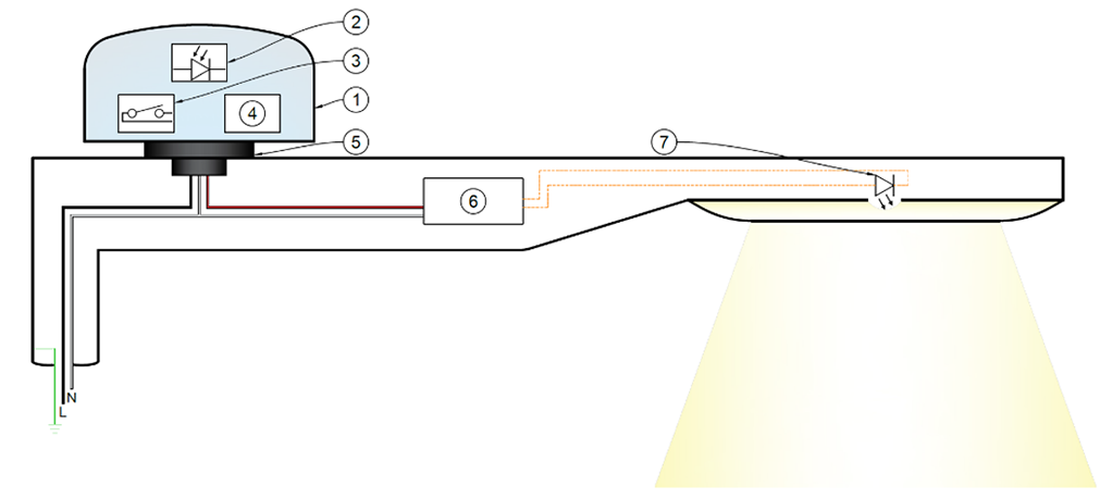
Over a decade ago, most streetlights were incandescent with photocells to turn them off during daylight hours. The ANSI C136.10 Standard for Roadway and Area Lighting Equipment provided a common platform for the interchangeability of photocontrols and receptacles based on AC line voltage with 3-pole connections. In North America, the roadway and area lighting market developed ANSI C136.10 as the standard interface, while it became the de facto standard in much of the world.

(1) Control Device – ANSI C136.10 Certified; (2) Photodiode; (3) Switched Voltage to LED Driver; (4) Power Supply Unit (PSU); (5) ANSI C136.10 Interface; (6) LED Driver; (7) Light-Emitting Diode (LED) Module.


ANSI C136.41
Dimmable Photocontrols
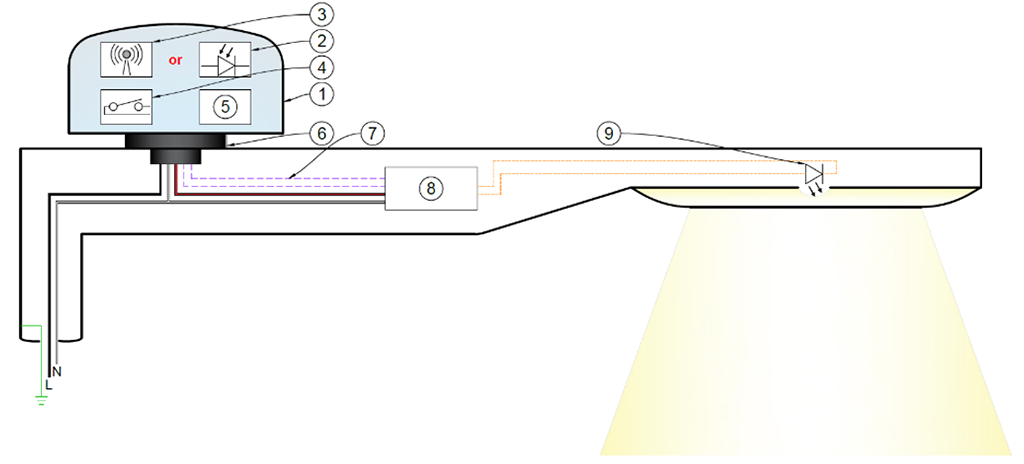
As energy costs have risen and LED technology has become more prevalent, ANSI C136.41 was developed to define devices and receptacles for increasing the efficiency of roadway luminaires. Created to be backwards compatible with existing lighting systems, this standard maintains the 3-pole line voltage connection and adds contacts for signal output. This interface allows for either digital or analog dimming control by a photodiode and an Astro-clock or motion sensor.
The architecture is designed to have grid power routed into ANSI C136.41 photocontrol and will switch that power to the LED driver. An internal power supply unit (PSU) converts that grid power to a logical voltage to power the controls. Often in North America, the dimming signal is analog (0-10 V) which is perceived to be inexpensive and reliable. Networking of the streetlights is achieved through a variety of different wireless protocols.
The ANSI C136.41 Standard does not provide many details about how to include sensor inputs into luminaires. The wide variety of wiring configuration choices makes it challenging to optimize components. Also, the 0-10 V analog control output limits the lighting fixture to only one input. However, there is considerable effort to include the D4i protocol, based on DALI-2, in future standard updates to address this.

(1) Control Device – ANSI C136.10 Certified; (2) Photodiode; (3) Wireless Communication to the Cloud; (4) Switched Line Voltage to LED Driver; (5) Power Supply Unit (PSU); (6) ANSI C136.10 Interface; (7) Dimming Signal – Analog or Digital; (8) LED Driver; (9) Light-Emitting Diode (LED) Module.

 e
e
 e
e
 e
e
 e
e
 e
e
 e
e
 e
e

 e
e
 e
e
 e
e


